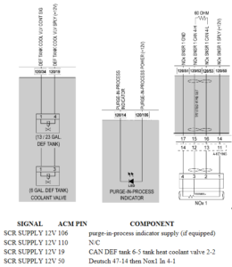
| Description | High Side Digital Output Circuit Shorted to Power |
| Monitored Parameter | High Side Digital Output |
| Typical Enabling Conditions | Always on |
| Monitor Sequence | None |
| Execution Frequency | Continuous when enabling conditions met |
| Typical Duration | 2 Seconds |
| Dash Lamps | MIL, CEL |
| Engine Reaction | None |
| Verification | Key Cycle |
TROUBLESHOOTING:
- Check for multiple codes. Is fault code SPN 3216/FMI 13 or SPN 3490/FMI (any) present along with SPN 5016/FMI 3?
- Yes; repair the other fault code first.

- Yes; repair the other fault code first.
- Turn the ignition OFF.
- Disconnect the Aftertreatment Control Module (ACM) 120-pin connector.
- Inspect the ACM 120-pin harness connector for bent, spread or corroded pins. Is any damage found?
- Yes; repair as necessary. Verify repair.
- No; Go to step 5.
- NOTE: Multiple fault codes will set with the ACM 120-pin connector disconnected. Disregard other fault codes at this time.
- Turn the ignition ON (key ON, engine OFF) and clear fault codes. Does SPN 5016/FMI 3 become active?
- Yes; replace the ACM. Refer to OEM procedures.
- No; Go to step 6.
- Measure the voltage between pin 19 of the 120-pin ACM connector, harness side, and battery ground. Is any voltage present?
- Yes; repair the short to power between pin 19 of the 120-pin ACM connector and pin 2 of the DEF coolant valve connector. Verify repair.
- No; Go to step 7.
- Measure the voltage between pin 50 of the 120-pin ACM connector, harness side, and battery ground. Is any voltage present?
- Yes; repair the short to power between pin 50 of the 120-pin ACM connector and pin 1 of the NOx inlet sensor connector. Verify repair.
- No; Go to step 11.
- Is the vehicle equipped with a purge-in-process indicator?1. Yes; Go to step 9.
- Measure the voltage between pin 106 of the 120-pin ACM connector, harness side, and battery ground. Is any voltage present?
- Yes; repair the short to power between pin 106 of the 120-pin ACM connector and pin 2 of the DEF Purge-in-Process indicator. Verify repair.
- No; Go to step 10.
- NOTE: ACM Pin 110 is not populated from the factory. The 120-pin ACM connector should be equipped with a cavity plug in the 120-pin connector cavity #110.
- Inspect connector cavity#110 of the 120-pin ACM connector, harness side. Is a wire populated in cavity #110?
- Yes; repair the short to power on pin 110 of the 120-pin ACM connector. Repair connector as needed. Verify repair.
- No; replace the ACM. Repair the connector as needed. Verify repair.
- Inspect connector cavity #106 of the 120-pin ACM connector, harness side. Is a wire populated in connector cavity #106?
- Yes; repair the short to power on pin 106 of the 120-pin ACM connector. Repair connector as needed. Verify repair.
- No; Go to step 12.
- Inspect connector cavity#110 of the 120-pin ACM connector, harness side. Is a wire populated in cavity #110?
- Yes; repair the short to power on pin 110 of the 120-pin ACM connector. Repair connector as needed. Verify repair.
- No; replace the ACM. Verify repair.