Author Archives: Mechanic

164/1 QUANTITY CONTROL VALVE LOW SIDE DRIVER ERROR

Published / by Mechanic / Leave a Comment

EPA07/10/GHG14 DDEC VI/10 Electronics and Troubleshooting Manual (DDC-SVC-MAN-0084) | 87 SPN 164 (MCM) (EPA07;EPA10;GHG14) | 87.2 SPN 164/FMI 1 – EPA07 – EPA10 – GHG14

Description Quantity Control Valve (Low Side) Error
Monitored Parameter Quantity Control Valve (QCV)
Typical Enabling Conditions Always Enabled
Monitor Sequence None
Execution Frequency Continuous when enabling conditions met
Typical Duration 2 Seconds
Dash Lamps MIL, CEL
Engine Reaction Derate 25%
Verification Engine Idle (1 minute)

This condition can occur when:

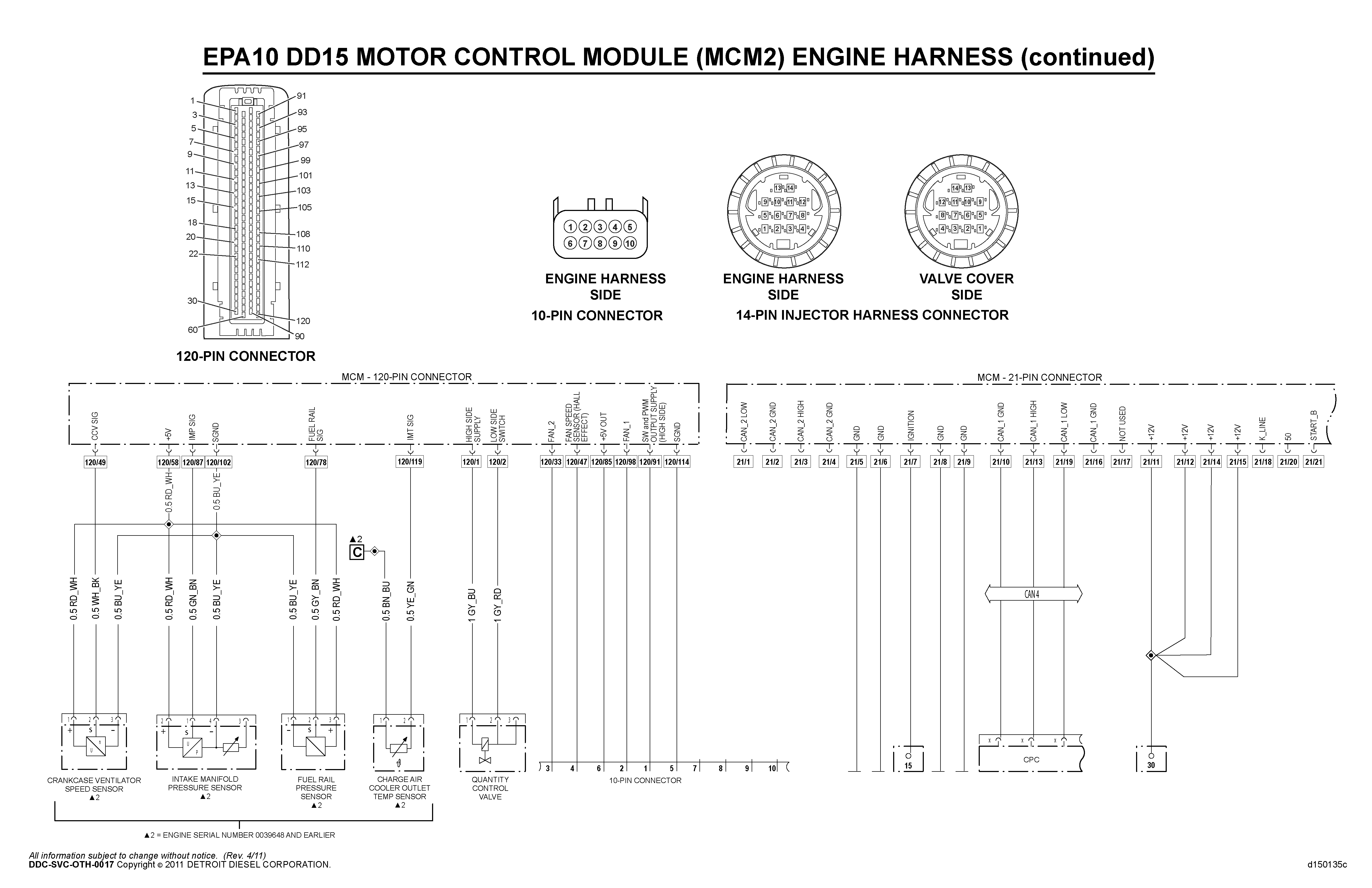
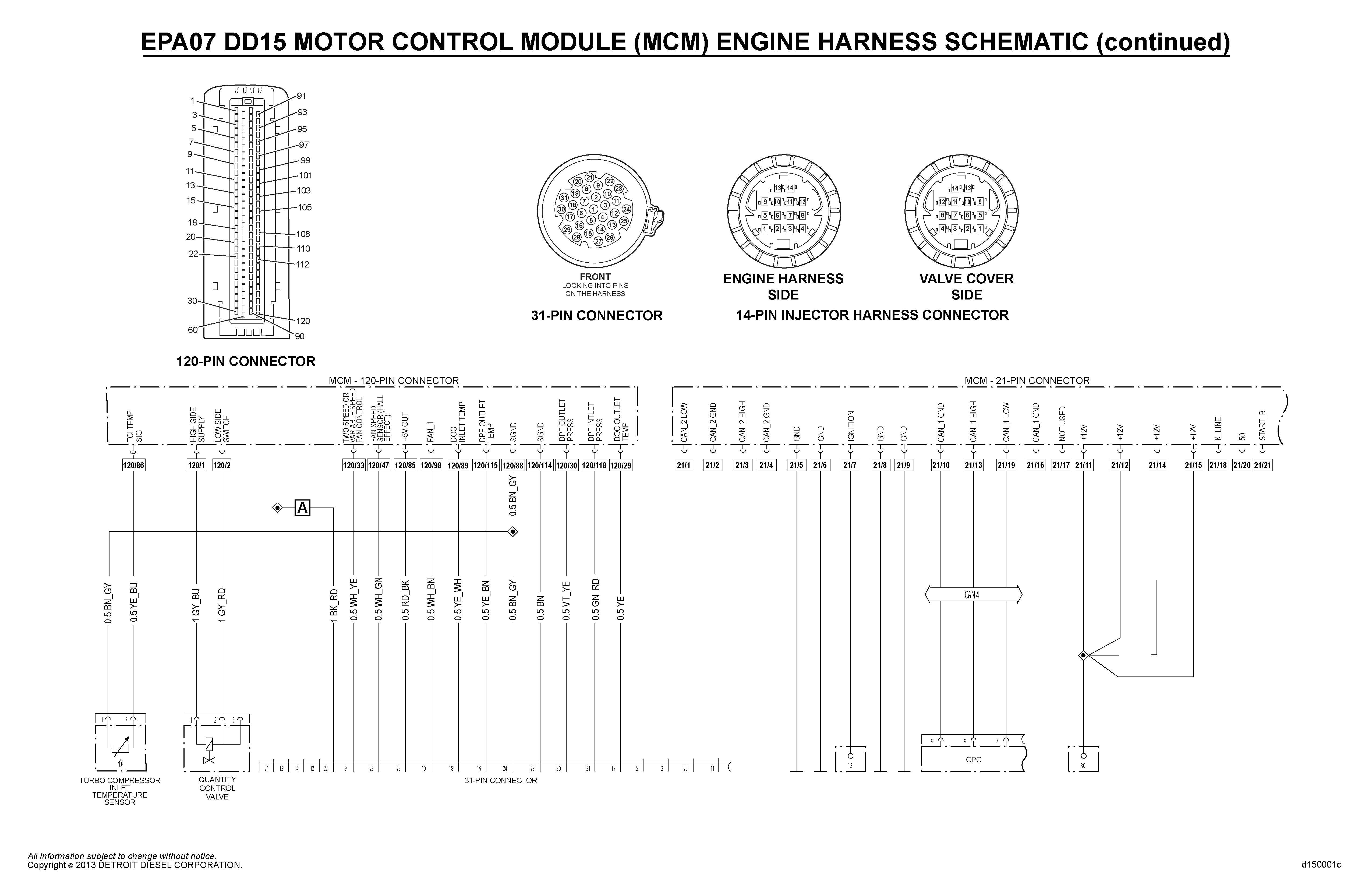
  • Motor Control Module (MCM) pin 2 circuit is shorted to power
  • Internal short of the quantity control valve

d150002a

Check as follows:

    1. Turn the ignition OFF.


    1. Disconnect the QCV harness connector.


    1. Inspect the harness connector for signs of damage: bent, spread, broken, corroded or unseated (push out) pins and signs of moisture in the connector or wire damage near the connector.
        1. If signs of damage are present, repair as necessary.
      1. If no signs of damage are present. Go to step 4.


    1. Ensure the multimeter or Digital Voltage Ohm Meter (DVOM) resistance is set to zero.
        1. If meter can auto–zero, perform this function before making a resistance measurement.
      1. If meter cannot auto–zero, note the resistance of the leads and subtract it from the measurement taken. Go to step 5.


    1. Measure the resistance across pins 1 and 2 of the QCV.
        1. If the resistance is between 1.0 ohm and 2.0 ohms, Go to step 6.
      1. If resistance is NOT between 1.0 ohm and 2.0 ohms, replace the QCV.
        Refer to section “Removal of the Quantity Control Valve – Three-Filter System”
        Refer to section “Removal of the Quantity Control Valve – Two-Filter System” .


    1. Disconnect the 120-pin MCM connector.


    1. Inspect the harness connector for signs of damage: bent, spread, broken, corroded or unseated (push out) pins and sign of moisture in the connector or wire damage near the connector.
        1. If signs of damage are present, repair as necessary.
      1. If no signs of damage are present, Go to step 8.


  1. Measure the resistance between pins 1 and 3 of the QCV harness connector.
      1. If the resistance is greater than 10k ohms, replace the MCM. Refer to section “Removal of the Motor Control Module” .
    1. If the resistance is less than 10k ohms, repair the short circuit between pins 1 and 2 of the QCV and pins 1 and 2 of the MCM 120-pin connector.

3711/31 HIGH IDLE REGENERATION (ABORTED) LOW EXHAUST TEMPERATURE

Published / by Mechanic / Leave a Comment

EPA07/10/GHG14 DDEC VI/10 Electronics and Troubleshooting Manual (DDC-SVC-MAN-0084) | 416 SPN 3711 (MCM) (EPA10;GHG14) | 416.1 SPN 3711/FMI 31 – EPA10 – GHG14

The fault indicates that the High Idle Regeneration (HIR) was aborted due to the Diesel Oxidation Catalyst (DOC) inlet temperature not reaching the minimum of 270°C (518°F) to initiate dosing during an HIR. The CEL and MIL lamps will remain ON until the fault is resolved or a successful regeneration is completed.

Show/Hide Checkboxes


    1. Connect DiagnosticLink® .


    1. Is the vehicle an EPA10 model?
        1. Yes; Go to step 3.
      1. No; Go to step 4.


    1. Is the Motor Control Module (MCM) software level 7.5.0.108 with fuel map ZGS 002 (DD15/16) & ZGS 003 (DD13) or higher?
        1. Yes; Go to step 4.
      1. No; update device software and then Go to step 4.


    1. Check fault codes; are SPN 3242/FMI 8 or SPN 3242/FMI 20 active or previously active?
        1. Yes; troubleshoot these codes first.
      1. No; Go to step 5.


    1. Start the engine.


    1. Monitor the Diesel Oxidation Catalyst (DOC) inlet temperature sensor, the DOC outlet temperature sensor. Continue idling for 10 minutes. Is the DOC inlet temperature drifted low?
        1. Yes; replace the DOC inlet temperature sensor and perform an HIR.
      1. No; Go to step 7.


    1. Using DiagnosticLink, perform an Intake Throttle Service Routine. Is the commanded position achieved?
        1. Yes; Go to step 8.
      1. No; replace the Intake Throttle Valve (ITV).


    1. Inspect the exhaust system for leaks.
        1. If a leak is found, repair as necessary.
      1. If no leaks are found, Go to step 9.


    1. Pressurize the intake tract and inspect for leaks.
        1. If a leak is found, repair as necessary.
      1. If no leaks are found, Go to step 10.


    1. Perform a Parked Regen. Once the ITV closes, view the Inlet Manifold Pressure (IMP) reading. Is the reading less than 23 PSIa (2.59 bar [37.7 psi])?
        1. No; inspect the ITV. Also for DD13 engines, the wastegate is command “on” during a Parked Regen; inspect the wastegate actuator and the plumbing to and from the actuator.
      1. Yes; Go to step 11.


    1. View the Jake Brake® -1 (PWM 13). Is the MCM commanding Jake Brake 1 on?
        1. Yes; Go to step 12.
      1. No; the oil temperature may be too cold. The oil temperature needs to be above 50ºC (122°F) for the Jake Brakes to turn on.


    1. Using DiagnosticLink during the regen, view AS087 Actual Fuel Mass. Is the fuel mass above 100 mg/st?
        1. Yes; send in the log file to the Detroit™ Customer Support Center at CSC@daimler.com. Call 800-445-1980 for further analysis and instruction.
      1. No; Go to step 13.


    1. Install a test MCM using the extension harness and perform a regen. Is the fuel mass above 100 mg/st?
        1. Yes; replace the MCM.
      1. No; Go to step 14.


    1. Remove the valve cover. Inspect the front top of the exhaust rocker arm shaft. It should state “TOP FRONT”. Refer to section “Checking for Poor Engine Brake Performance” .
        1. If the rocker arm does NOT state “TOP FRONT” then remove and inspect it for correct installation and part.
      1. If the rocker arm does state “TOP FRONT”, Go to step 15.


    1. Using DiagnosticLink, Service Routines, Cylinder Cut-Out, cut out cylinders one, two, and three. On the Jake Brake solenoid there is a button to push called the Jake Brake Override. Push and hold the Jake Brake override button. Does the engine quit running?
        1. Yes; replace the exhaust rocker arm shaft. The plug in the rocker arm shaft is missing (cannot be seen), causing oil to activate the rear Jake Brakes.
      1. No; Go to step 16.


    1. When the Jake override button is pushed down, do you see all the Jake Brake rocker arm pistons come out of the Jake Brake rocker arms for cylinders one, two, and three?
        1. Yes; replace the solenoid and assemble the engine to perform a regen.
      1. No; Go to step 17.


    1. Remove the front (Bank 1) engine brake solenoid from the cam frame. This will require the removal of the front injector harness. Make sure both injector harnesses (front and rear) are unplugged. Crank the engine; is there oil coming out of the port in the cam frame housing?
        1. Yes; replace the solenoid. Go to step 18.
      1. No; replace the cam frame housing.


  1. Push on the Jake Brake override button again. Do the Jake Brake pistons activate for cylinders one, two and three?
      1. Yes; assemble the engine and try a regen.
    1. No; remove the Jake Brake solenoid and the exhaust rocker arm shaft. Blow compressed shop air through the cam frame to the solenoid gallery, inspecting for a blockage. Remove the rockers for cylinders one, two and three. Blow compressed shop air through the rocker arm inspecting for blockage. If no blockage is found, replace the Jake Brake rockers that did not have the pistons activate.

4374/0 UNDER PRESSURIZED DIESEL EXHAUST FLUID SYSTEM

Published / by Mechanic / Leave a Comment

EPA07/10/GHG14 DDEC VI/10 Electronics and Troubleshooting Manual (DDC-SVC-MAN-0084) | 505 SPN 4374 (ACM) (GHG14) | 505.1 SPN 4374/FMI 0 – GHG14

Description This Code Sets When the Diesel Exhaust Fluid (DEF) Pump Speed is Higher than Normal For a Given DEF Pressure
Monitored Parameter DEF Pump Speed, DEF Pressure
Monitor Sequence None
Execution Frequency Continuous When Enabling Conditions Met
Typical Duration Continuous Until Resolved
Dash Lamps MIL, CEL
Engine Reaction Derate 25%
Verification SCR ADS Self-Check

Possible causes:

  • Restriction in the DEF line between the DEF tank and the DEF pump
  • Restriction in the DEF line between the DEF pump and the DEF dosing unit
  • Air in the DEF line between the DEF tank and the DEF pump
  • Restriction in the DEF pump
  • Failed DEF pump

Check as follows:

NOTICE:

Customers in colder climates where winter ambient air temperatures generally stay below -11° C (12°F) need to verify that the DEF is not frozen before troubleshooting this fault code.

    1. Connect DiagnosticLink® .

    1. Turn the ignition ON (key ON, engine OFF).

    1. Check for multiple codes. Are codes SPN 4334/FMI 3, 4, SPN 4375/FMI 3, 4, or SPN 3361/FMI 3, 4, 5 also present?
        1. Yes; diagnose and repair the other fault codes first. Verify repair.

      1. No; Go to step 4.

    1. Turn the ignition OFF.

    1. Inspect the DEF tank vent tube. Is there any blockage or restriction?
        1. Yes; clear the restricted vent tube. Go to step 6.

      1. No; Go to step 6.

    1. Using DEF test strip A0005850202, check for diesel fuel or oil contamination of the DEF fluid. Does the test strip indicate contamination?
        1. Yes; replace the following components and refill the system with new DEF:
          • DEF tank
          • DEF tank header
          • DEF supply line from the DEF tank to the DEF pump
          • DEF line from the DEF pump to the DEF dosing unit
          • DEF return line from the DEF dosing unit to the DEF tank
          • DEF pump
          • DEF dosing unit

      1. No; Go to step 7.

    1. Inspect the DEF line that runs from the DEF pump to the DEF dosing unit. Is the DEF line damaged, pinched, or kinked?
        1. Yes; replace the DEF line from the DEF pump to the DEF dosing unit.

      1. No; Go to step 8.

    1. Inspect the DEF line that runs from the DEF tank to the DEF pump. Is the DEF line damaged, pinched, or kinked?
        1. Yes; replace the DEF line from the DEF tank to the DEF pump.

      1. No; Go to step 9.

    1. Disconnect the DEF supply line at the dosing unit. Fill the graduated cylinder supplied in DEF test kit (P/N: W060589001900) with water. Place the end of the DEF line into the graduated cylinder as far as possible.
NOTE: Place the graduated cylinder in a secondary container to catch over flowing DEF fluid, making sure you still have clear sight of the end of the DEF line.

    1. Using DiagnosticLink, perform the Selective Catalyst Reduction Airless Dosing System (SCR ADS) Self-Check routine. When the service routine is running, visually inspect the DEF line for continuous air bubbles coming from the line and DEF flow.

    1. Were any bubbles coming from the DEF pump supply line indicating a crack in the DEF pump feed line?
        1. Yes; replace the DEF supply line from the DEF tank to the DEF pump. Verify repair.

      1. No; Go to step 12.
NOTICE:

The RS SUPPLY KIT contains all the necessary parts for steps 12-15.

    1. Using the DEF/Doser Kit , replace the DEF pump module filter. Go to step 13.

    1. Replace the DEF pump inlet screen. Go to step 14.

    1. Replace DEF Pressure Relief Valve (PRV).  Go to step 15.

    1. Replace DEF dosing unit inlet screen. Go to step 16.
NOTE: If air pressure is greater than 827 kPa (120 psi), use a pressure regulator.

    1. Prime pump with shop air. Using a rubber tipped air gun to seal around the DEF pump inlet fitting, apply clean regulated shop air to the DEF pump inlet fitting for three to five seconds.
      d140723a

    1. Connect all DEF lines and electrical connections. Go to step 18.

  1. Perform Selective Catalytic Reduction Airless Dosing System (SCR ADS) Self-Check Routine to prime the system. Did the SCR ADS test pass?
      1. Yes; clear the codes and release the vehicle.

    1. No; replace the DEF pump. 

3556/18 EPA10 DIESEL OXIDATION CATALYST OUTLET TEMPERATURE LOW

Published / by Mechanic / 2 Comments on 3556/18 EPA10 DIESEL OXIDATION CATALYST OUTLET TEMPERATURE LOW

EPA07/10/GHG14 DDEC VI/10 Electronics and Troubleshooting Manual (DDC-SVC-MAN-0084) | 372 SPN 3556 (ACM) (EPA10) | 372.2 SPN 3556/FMI 18 – EPA10

Description This code sets when the exhaust temperature does not increase above the modeled threshold when the low temp regeneration is enabled.
Monitored Parameter Diesel Oxidation Catalyst (DOC) outlet temperature sensor
Typical Enabling Conditions Low temperature regeneration enabled, 1100 to 2050 rpm, 50% to 100% engine load.
Monitor Sequence None
Execution Frequency Continuous When Enabling Conditions Met
Typical Duration 20 seconds
Dash Lamps MIL, CEL
Engine Reaction None
Verification Low Temp Regeneration

Check as follows:

    1. Connect DiagnosticLink® . Go to step 2.

    1. Turn the key ON (Key ON, Engine OFF). Go to step 3.

    1. Check for multiple codes. Are there DOC outlet temperature sensor stuck fault codes or DOC outlet temperature sensor circuit fault codes present?
        1. Yes; diagnose the other fault codes first. Verify repair.

      1. No; Go to step 4.

    1. Are there any Hydrocarbon (HC) doser low pressure fault codes present?
        1. Yes; diagnose HC doser low pressure fault codes first. Verify repair.

      1. No; Go to step 5.

    1. Perform the low temperature Aftertreatment Device (ATD) regeneration; Go to step 6.

    1. After the low temp ATD regeneration has run for 20 minutes, monitor the DOC outlet temperature sensor reading. Is the DOC outlet temperature sensor reading within 25°C (45°F) of the other exhaust temperature sensor readings?
        1. Yes; Go to step 7.

      1. No; replace the DOC outlet temperature sensor. Verify repair.

  1. Visually inspect the exhaust system for leaks. Are there exhaust leaks present?

      1. Yes; repair the exhaust leaks. Verify repair.


    1. No; replace the HC doser block. Verify repair.

5488/4 DIESEL EXHAUST FLUID LINE HEATER 5 CIRCUIT FAILED LOW

Published / by Mechanic / Leave a Comment

GHG17 Heavy Duty Troubleshooting Manual (DDC-SVC-MAN-0191) | 347 SPN 5488 (ACM) (GHG17) | 347.2 SPN 5488/FMI 4 – GHG17

Description Line Heater 5 Circuit Failed Low
Monitored Parameter Line Heater 5 Circuit
Typical Enabling Conditions Always on
Monitor Sequence None
Execution Frequency Continuous when enabling conditions met
Typical Duration 2 Seconds
Dash Lamps MIL, CEL
Engine Reaction None
Verification Output Component Test

TROUBLESHOOTING:

  1. Turn the ignition OFF.
  2. Disconnect the line heater/Dosing Unit 8-pin connector.
  3. Inspect the sensor harness for bent, spread or corroded pins.
    1. If the pins are bent, spread or corroded, repair as necessary.
    2. If the connector shows no signs of damage, Go to step 4.
  4. Disconnect the ACM 120-pin connector.
  5. Measure the resistance between pin 3 on the harness side of the line heater 8-pin connector and ground.
    1. If the resistance is less than 10K ohms, repair the wire between pin 3 of the line heater 8-pin connector and pin 22 of the ACM 120-pin connector.
    2. If the resistance is greater than 10K ohms, replace the Dosing Unit.

DOSING UNIT

5016/3 EPA10 COOLANT VALVE SUPPLY VOLTAGE FAILED HIGH

Published / by Mechanic / Leave a Comment
Description High Side Digital Output Circuit Shorted to Power
Monitored Parameter High Side Digital Output
Typical Enabling Conditions Always on
Monitor Sequence None
Execution Frequency Continuous when enabling conditions met
Typical Duration 2 Seconds
Dash Lamps MIL, CEL
Engine Reaction None
Verification Key Cycle

TROUBLESHOOTING:

  1. Check for multiple codes. Is fault code SPN 3216/FMI 13 or SPN 3490/FMI (any) present along with SPN 5016/FMI 3?
    1. Yes; repair the other fault code first.COOLANT VALVE DIAGRAM
  2. Turn the ignition OFF.
  3. Disconnect the Aftertreatment Control Module (ACM) 120-pin connector.
  4. Inspect the ACM 120-pin harness connector for bent, spread or corroded pins. Is any damage found?
    1. Yes; repair as necessary. Verify repair.
    2. No; Go to step 5.
  5. NOTE:  Multiple fault codes will set with the ACM 120-pin connector disconnected. Disregard other fault codes at this time.
  6. Turn the ignition ON (key ON, engine OFF) and clear fault codes. Does SPN 5016/FMI 3 become active?
    1. Yes; replace the ACM. Refer to OEM procedures.
    2. No; Go to step 6.
  7. Measure the voltage between pin 19 of the 120-pin ACM connector, harness side, and battery ground. Is any voltage present?
    1. Yes; repair the short to power between pin 19 of the 120-pin ACM connector and pin 2 of the DEF coolant valve connector. Verify repair.
    2. No; Go to step 7.
  8. Measure the voltage between pin 50 of the 120-pin ACM connector, harness side, and battery ground. Is any voltage present?
    1. Yes; repair the short to power between pin 50 of the 120-pin ACM connector and pin 1 of the NOx inlet sensor connector. Verify repair.
    2. No; Go to step 11.
  9. Is the vehicle equipped with a purge-in-process indicator?1. Yes; Go to step 9.
  10. Measure the voltage between pin 106 of the 120-pin ACM connector, harness side, and battery ground. Is any voltage present?
    1. Yes; repair the short to power between pin 106 of the 120-pin ACM connector and pin 2 of the DEF Purge-in-Process indicator. Verify repair.
    2. No; Go to step 10.
  11. NOTE:  ACM Pin 110 is not populated from the factory. The 120-pin ACM connector should be equipped with a cavity plug in the 120-pin connector cavity #110.
  12. Inspect connector cavity#110 of the 120-pin ACM connector, harness side. Is a wire populated in cavity #110?
    1. Yes; repair the short to power on pin 110 of the 120-pin ACM connector. Repair connector as needed. Verify repair.
    2. No; replace the ACM. Repair the connector as needed. Verify repair.
  13. Inspect connector cavity #106 of the 120-pin ACM connector, harness side. Is a wire populated in connector cavity #106?
    1. Yes; repair the short to power on pin 106 of the 120-pin ACM connector. Repair connector as needed. Verify repair.
    2. No; Go to step 12.
  14. Inspect connector cavity#110 of the 120-pin ACM connector, harness side. Is a wire populated in cavity #110?
    1. Yes; repair the short to power on pin 110 of the 120-pin ACM connector. Repair connector as needed. Verify repair.
    2. No; replace the ACM. Verify repair.