Author Archives: Mechanic

3480/2 EPA 07/10/GHG14 HYDROCARBON DOSER FUEL LINE PRESSURE LOW

Published / by Mechanic / Leave a Comment

Hydrocarbon Doser Fuel Line Pressure Low SPN 3480/FMI 2

Description Hydrocarbon (HC) Doser Fuel Line Pressure Low

Monitored Parameter HC Doser Fuel Line Pressure

Typical Enabling Conditions Dosing Enabled

Execution Frequency Continuous When Enabling Conditions Met

Typical Duration One Minute
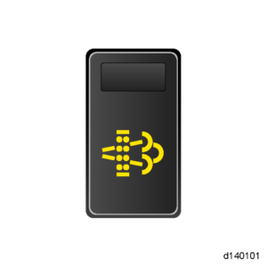
Dash Lamps MIL, CEL

Engine Reaction Derate 10%

Verification Parked Regeneration

TROUBLESHOOTING:

  1. Are there any fuel system faults present?
    1.     Yes; repair fault with the highest priority listed below. Verify repair. 3480/3, or 4 4077/3, or 4 3480/1, 4077/14
    2. No; Go to step 4.
  2. Start the engine.
  3. Using DiagnosticLink, perform two back-to-back “Purge Hydrocarbon Doser” service routines to help improve the chances of identifying a leak.
  4. Turn the ignition OFF.
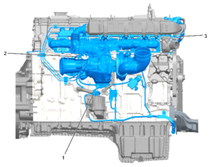
  5. Visually inspect the fuel line between the HC doser block assembly and fuel doser injector valve for any sign of external fuel leaks. Are any external leaks present?
    1. 1. Yes; replace the HC doser injector valve fuel supply line. Go to step 8.
    2. No; replace the HC fuel doser injector valve. Refer to section “Removal of the Hydrocarbon Doser Fuel Injector Valve” . Go to step 8.
  6. Turn the ignition ON and start the engine.
  7. Clear fault codes.
  8. Perform a parked regeneration to verify the repair. Did SPN 3480/FMI 2 become active during regeneration?
    1.      Yes; replace doser block. Refer to section “Removal of the Hydrocarbon Doser Fuel Injector Valve” . Verify repair.
    2.    No; release vehicle.

Coolant in Oil

Published / by Mechanic / 2 Comments on Coolant in Oil

NOTE:  Appearance of oil will be brown and have a milky-like state. Oil may be above recommended level as well.

  1. Pressurize the cooling system. Does the system hold pressure?
    1. Yes, the system holds pressure; Go to step 7.
    2. No; the system leaks down; Go to step 2.
  1. Remove the oil pan. Pressurize the cooling system. Where is coolant leaking from?
    1. Between the piston and liner; Go to step 3.
    2. Between the liner and block; Go to step 4.
    3. From the gear train or an oil return passage; Go to step 5.
    4. No coolant leaks are found present; Go to step 7.
  1. Remove the cylinder head and inspect for a failed cylinder kit. Was a failed cylinder kit found?
    1. Yes; replace lower end bearing kit, make necessary repairs, flush cooling system, and change engine oil.
    2. No; Go to step 4.
  1. Remove the cylinder liner where the leak was found. Was damage found?
    1. Yes; replace lower end bearing kit, make necessary repairs, flush cooling system, and change engine oil.
    2. No; Go to step 7.
  1. Pressure test the Oil Cooler. Were leaks found?
    1. Yes, leaks are found. Replace lower end bearing kit, make necessary repairs, flush cooling system, and change engine oil.
    2. No, leaks are not found; Go to step 6.
  1. Remove the cylinder head and inspect the cylinder head gasket for torn or debonded grommets.
    1. If damage is found, replace lower end bearing kit, make necessary repairs, flush cooling system, and change engine oil.
    2. If no damage is found, Go to step 7.
  1. Is fault code SPN 100/FMI 1 Low Engine Oil Pressure present?
    1. Yes; Inspect the Main and Connecting Rod Bearings.
    2. No; troubleshooting complete.

DD15 Engine Sensor Descriptions

Published / by Mechanic / Leave a Comment

Factory-installed Sensors

The sensors integrated into the factory-installed Engine Harness are listed below.

Sensor Type Description
Camshaft Position (CMP) sensor Indicates a specific cylinder in the firing order.
Crankshaft Position (CKP) sensor Senses crankshaft position and engine speed for functions such as fuel control strategy.
Diesel Particulate Filter (DPF) inlet pressure sensor Sensor measures pressure between the Diesel Oxidation Catalyst (DOC) and the Diesel Particulate Filter (DPF) in the aftertreatment assembly located in the exhaust system of the vehicle.
DPF outlet pressure sensor Sensor measures pressure on the outlet of the after-treatment device in the exhaust system of the vehicle. Located after the DPF that is within the aftertreatment device.
DPF outlet temperature sensor Temperature measured at the outlet of the after-treatment system that is installed within the exhaust system of the vehicle. Located after the DPF that is within the aftertreatment device.
Diesel Oxidation Catalyst (DOC) inlet temperature sensor Temperature measured at the inlet of the aftertreatment device in the exhaust system of the vehicle. Located before the DOC that is within the aftertreatment device.
DOC outlet temperature sensor Temperature measured between the DOC and the DPF in the aftertreatment assembly located in the exhaust system of the vehicle.
Exhaust Gas Recirculation (EGR) Delta Pressure (Delta P) sensor Senses EGR pressure for EGR control.
EGR temperature sensor Senses EGR exhaust temperature after EGR cooler. Used for EGR system diagnosis.
Engine Coolant Temperature (ECT) sensor Senses coolant temperature for functions such as engine protection, fan control and engine fueling.
Engine Oil Pressure (EOP) sensor Senses gallery oil pressure for functions such as engine protection.
Engine Oil Temperature (EOT) sensor Senses oil temperature for functions such as reducing variation in fuel injection and fan control.
Fuel compensation pressure sensor Compensates fuel line pressure.
Fuel rail pressure sensor Senses high pressure fuel in the fuel rail
Intake Manifold Pressure (IMP) sensor Senses turbocharger boost for functions such as smoke control and engine protection.
Intake Manifold Temperature (IMT) sensor Senses boost temperature.
Low pressure fuel sensor Senses pressure in the low pressure fuel circuit
Supply fuel temperature sensor Senses fuel temperature for functions such as engine fueling.
Turbocharger compressor temperature out sensor Senses turbocharger out air temperature.
Turbocharger Speed Sensor (TSS) Monitors turbocharger speed.
Water-in-Fuel (WIF) sensor Detects water in the fuel filter that alerts the owner/driver that the fuel filter needs to be dried out.

OEM-installed Sensors

All sensors must be of the proper type and continuously monitor vehicular and environmental conditions, so the MCM can react to changing situations. The OEM is responsible for installing the sensors listed in this table.

Sensor Function
Ambient Air Temperature (AAT) sensor Senses ambient air temperature specifically for the ambient air temperature override disable feature or for Optimized Idle (OI).
Engine Coolant Level (ECL) sensor Senses coolant level for engine protection.
Turbocharger compressor inlet temperature sensor Senses the temperature of the turbocharger compressor inlet.
Vehicle Speed Sensor (VSS) Senses vehicle speed for cruise control and vehicle speed limiting.

DD15 EPA10 Engine Sensor Locations

Published / by Mechanic / 3 Comments on DD15 EPA10 Engine Sensor Locations

epa10-dd15-left-side-sensors

GET THE BEST FREIGHTLINER CASCADIA FLOOR MATS FOR WINTER

  1. Engine Oil Pressure Sensor
  2. Engine Oil Temperature Sensor
  3. Coolant Inlet Temperature Sensor
  4. Intake Throttle Valve
  5. Intake Manifold Pressure / CAC Temp Sensor
  6. Fuel Rail Pressure Sensor
  7. EGR Delta P Sensor
  8. LPPO Fuel Pressure Sensor
  9. Intake Manifold Temperature Sensor
  10. Camshaft Position Sensor
  11. Fuel Compensation Pressure Sensor
  12. Fuel Doser Line Pressure Sensor
  13. Electronic Dosing Valve
  14. Fuel Cutoff Valve
  15. Crankshaft Position Sensor
  16. Supply Fuel Temperature Sensor
  17. Water-In-Fuel Sensor

SAVE MONEY ON FUEL FREIGHTLINER CASCADIA

epa10-dd15-right-side-sensors

  1. Oil Separator Speed Sensor
  2. EGR Actuator
  3. Coolant Outlet Speed Sensor

All 1 Box Sensor Locations

Published / by Mechanic / 5 Comments on All 1 Box Sensor Locations

EPA10 1 BOX

  1. Diesel Oxidation Catalyst Outlet Temperature Sensor
  2. Diesel Oxidation Catalyst Inlet Pressure Sensor Tube
  3. Diesel Oxidation Catalyst Inlet Temperature Sensor
  4. Front Heat Shield
  5. Diesel Exhaust Fluid Nozzle
  6. Exhaust Outlet
  7. Diesel Exhaust Fluid Metering Unit
  8. Exhaust Inlet
  9. Selective Catalytic Reduction (SCR Catalyst) Outlet Temperature Sensor
  10. Selective Catalytic Reduction (SCR Catalyst) Outlet NOx Sensor
  11. Selective Catalytic Reduction (SCR Catalyst) Inlet Temperature Sensor
  12. Selective Catalytic Reduction (SCR Catalyst) Inlet and Outlet NOx Sensors (microprocessor mounted)
  13. Diesel Particulate Filter Outlet Pressure Sensor Tube
  14. Selective Catalytic Reduction (SCR Catalyst) Inlet Temperature Sensor
  15. Selective Catalytic Reduction (SCR Catalyst) Inlet NOx Sensors
  16. 47-Pin Connector Harness
  17. Diesel Particulate Filter Outlet Pressure Sensor
  18. Diesel Oxidation Catalyst Inlet Pressure Sensor
  19. Sensor bridge

GET THE BEST FREIGHTLINER CASCADIA FLOOR MATS FOR WINTER

epa-10-1-box-sensor-locationsGHG14 1 BOX

  1. Diesel Oxidation Catalyst Outlet Temperature Sensor
  2. Diesel Oxidation Catalyst Inlet Pressure Sensor Tube
  3. Diesel Oxidation Catalyst Inlet Temperature Sensor
  4. Front Heat Shield
  5. Diesel Exhaust Fluid Dosing Unit
  6. Exhaust Outlet
  7. Exhaust Inlet
  8. Selective Catalytic Reduction (SCR Catalyst) Outlet Temperature Sensor
  9. Selective Catalytic Reduction (SCR Catalyst) Outlet NOx Sensor
  10. Selective Catalytic Reduction (SCR Catalyst) Inlet Temperature Sensor
  11. Selective Catalytic Reduction (SCR Catalyst) Inlet and Outlet NOx Sensors (microprocessor mounted)
  12. Diesel Particulate Filter Outlet Pressure Sensor Tube
  13. Selective Catalytic Reduction (SCR Catalyst) Inlet Temperature Sensor
  14. Selective Catalytic Reduction (SCR Catalyst) Inlet NOx Sensors
  15. 47-Pin Connector Harness
  16. Diesel Particulate Filter Outlet Pressure Sensor
  17. Diesel Oxidation Catalyst Inlet Pressure Sensor
  18. Sensor bridge.   SAVE MONEY ON FUEL FREIGHTLINER CASCADIAghg14-1-box-sensor-locations

How to do a Parked Regen

Published / by Mechanic / 14 Comments on How to do a Parked Regen

    1. Keep engine at slow idle (cannot be in Fast Idle or PTO Mode). Put transmission in neutral (if equipped with an automatic transmission, cycle it into gear and then back to neutral).
NOTICE:

Air tank pressure must be high enough for the parking brake switch to hold in the OFF position.

GET THE BEST FREIGHTLINER CASCADIA FLOOR MATS FOR WINTER

    1. Set park brake (cycle the park brake OFF then ON for CPC R21 or lower software).

    1. Press and release clutch pedal once per ignition cycle (if configured).

  1. Hold DPF Switch to the ON position for five seconds and then release (engine speed will increase and DPF lamp will go out). regen-buttonEPA07/10/GHG14 Exhaust – EGR – ATS Manual (DDC-SVC-MAN-0083) | 37 EPA10/GHG14 Aftertreatment System Overview | 37.9 Performing a Parked Regeneration – EPA10/GHG14When the parked regeneration request is accepted, the Diesel Particulate Filter (DPF) Regeneration lamp will turn ON one time for one second and then turn off for the remainder of the parked regeneration. The High Exhaust System Temperature (HEST) lamp will flash for one second every ten seconds and eventually become solid when the tailpipe temperature is above 525°C (977°F).The engine speed will increase to 1100 RPM for all DD Platform engines. The regeneration will take 30 to 40 minutes. The regeneration is complete when the engine returns to low idle and the DPF lamp remains OFF. The HEST lamp will remain ON, but the vehicle may be driven.

    NOTE: A parked regeneration will STOP and the engine will return to low idle if any of the following happens:

    SAVE MONEY ON FUEL FREIGHTLINER CASCADIA

    • The key is turned to the OFF position
    • The vehicle is put into gear
    • The clutch is cycled
    • The parking brake is released
    NOTE: If a parked regeneration is being performed to check NOx conversion, the calculated ambient temperature in the ACM (AS053) must be above 0°C (32°F) or the test will fail.
    NOTE: If the HEST LAMP is FLASHING, a regeneration is in process and the system is coming up to temperature.

How to Check Fault Codes DD15 Freightliner Cascadia

Published / by Mechanic / 5 Comments on How to Check Fault Codes DD15 Freightliner Cascadia

Follow these guidelines to check for fault codes on any Freightliner Cascaida with a DD15 engine.

  1. Key on, Engine off.
  2. Placed unit in neutral.
  3. Locate the square black button on the odometer screen.
  4. Using the black button cycle through the options displayed on the odometer reading until it reads “diagnose”.
  5. Hold the button until the display shows “faults”.
  6. From there it will show you the number of active faults in the system.
  7. Again using the black button cycle through the “faults” to observe the SPN and FMI.

3364/1 EPA10 Diesel Exhaust Fluid Quantity Final Warning

Published / by Mechanic / 1 Comment on 3364/1 EPA10 Diesel Exhaust Fluid Quantity Final Warning
Description Improper Diesel Exhaust Fluid (DEF) Quality Final Warning
Monitored Parameter DEF Quality
Typical Enabling Conditions DEF Refill Event Detected
Monitor Sequence None
Execution Frequency Continuous When Enabling Conditions Met
Typical Duration Two hours
Dash Lamps MIL, CEL, DEF Lamp Flash
Engine Reaction None
Verification Parked Regeneration


To clear the fault code, ambient air temperatures must be greater than 0°C (32°F).

  1. Connect DiagnosticLink® .
  2. Using refractometer from DEF Test Kit W060589001900, measure DEF percentage. Is DEF percentage between 28 and 36%?
    1. Yes; go to step 3.
    2. No; refer to appropriate manual for DEF tank cleaning/flushing procedure, then Go to step 12.
  3. Turn ignition ON (key ON, engine OFF).
  4. Compare DEF pressure to ambient air pressure (baro) and DEF air pressure. Is DEF pressure within 29.6 kPa (4.3 psi) of ambient air pressure (baro) and DEF air pressure?
    1. Yes; go to step 5.
    2. No; replace the DEF pressure sensor. Go to step 12.
  5. Visually check all DEF supply and air lines for physical damage (kinks, cracks, leaks, disconnects). Is any damage found?
    1. Yes; repair as necessary; Go to step 12.
    2. No; go to step 6.
  6. Perform a DEF quantity test service routine and record the amount of DEF fluid level dispensed. Is the dispensed DEF fluid level between 108 and 132 mL (3.65 and 4.46 oz)?
    1. Yes; go to step 12.
    2. No; go to step 7.
  7. Remove DEF air pressure and temperature sensors.
  8. Remove the DEF inlet delivery line and DEF air supply line from metering unit.
  9. Remove DEF nozzle from the Aftertreatment Device (ATD) box.
  10. Flush warm water into DEF air pressure and temperature sensor cavities in the DEF metering unit until water flows from the DEF inlet and DEF nozzle. Reinstall sensors and perform the DEF quantity test service routine. Is the dispensed DEF fluid level between 102 and 138 mL (3.45 to 4.66 oz)?
    1. Yes; Go to step 12.
    2. No; repeat flushing procedure. Go to step 11.
  11. Perform a DEF quantity test service routine and record the amount of DEF fluid level dispensed. Is the dispensed DEF fluid level between 102 and 138mL (3.45 to 4.66 oz)?
    1. Yes; Go to step 12.
    2. No; replace DEF Metering Unit. Go to step 12.
  12. Connect DiagnosticLink® . Monitor (chart) the following parameters:
    • ASL102 Engine Speed
    • AS018 Selective Catalyst Reduction (SCR) Inlet Temperature
    • AS019 SCR Outlet Temperature
    • AS035 SCR Inlet NOx Sensor
    • AS036 SCR Outlet NOx Sensor
    • AS101 NOx Conversion Efficiency
  1. Start engine and perform a parked regeneration. Retain the log file. Does the NOx conversion efficiency rise and stay above 70% (0.70) during the regeneration?
    1. Yes; clear faults and Go to step 17.
    2. No; Go to step 14.
  1. Disconnect the DEF doser electrical connector.

NOTE: Disregard SPN 3361/FMI 5 which will set with valve unplugged.

  1. Turn the ignition ON (key ON, engine OFF).
  2. Perform a low temperature Aftertreatment Device (ATD) check using DiagnosticLink to check for a drifted temperature sensor. Are the inlet NOx sensor and outlet NOx sensor readings within 50 Parts Per Million (PPM) of each other?
    1. Yes, Go to step 17.
    2. No, replace the SCR inlet NOx sensor. Go to step 18.
  3. Start the engine and perform a complete parked regeneration. The regen will burn off any DEF deposits in the aftertreatment. Verify repairs.
  4. Perform a low temperature Aftertreatment Device (ATD) check using DiagnosticLink to check for a drifted temperature sensor. Are the inlet NOx sensor and outlet NOx sensor readings within 50 Parts Per Million (PPM) of each other?
    1. Yes, clear faults and release vehicle.
    2. No, replace the SCR outlet NOx sensor. Verify repairs.

157/16 EPA07 EPA10 GHG14

Published / by Mechanic / Leave a Comment

The Motor Control Module (MCM) monitors the rail pressure and when rail pressure deviation is greater than 200 bar for eight seconds, the MCM sets the code. This fault can occur due to the conditions listed below:

  • External fuel leakage between the high pressure pump and fuel injectors
  • Pressure limiting valve leakage (internal)
  • Fuel filter integrity (loose caps, plugged filters)
  • Fuel supply issues (fuel level, fuel aeration, leaking fuel lines, fuel restrictions)
  • Intermittent loss of engine speed signal
  • High pressure pump internal failure
  • Fuel injector (amplifier or needle) leakage
  • Fuel Contamination
  • Rail pressure sensor
  • Motor Control Module (MCM)


Causes For Onebox/DPF Failures/ATD Checklist

Published / by Mechanic / 1 Comment on Causes For Onebox/DPF Failures/ATD Checklist

A common failure now on all EPA10 DD15 is becoming a one box and DPF failures, these are costly items to repair. To repair these failures correctly you must determine root cause for failure, as these parts will never fail on their own. Find the primary failed part and repair prior to replacing a onebox or DPF’s to prevent repeat failure down the road.

  1. Verify the air filter is installed correctly. Measure the Air Inlet Restriction with a manual gauge under 100% load (do not use the gauge on the air filter assembly). Is the Air Inlet Restriction greater than 18 H2 O”? Repair as required over restriction level.
  2. Pressurize the intake track, including the Charge Air Cooler (CAC) and associated piping, inspecting for leaks. Was a leak found? Repair for any leaks.
  3. Inspect for excessive oil coming out of the turbocharger compressor. If any oil is present Replace Turbo.
  4. With engine OFF, visually inspect the Exhaust Gas Recirculation (EGR) linkage for damage or limited travel. Repair for EGR component Failure.
  5. Using DiagnosticLink® , sweep the Intake Throttle Valve (ITV). Is the ITV stuck or is there limited travel? If a seized valve is found, repair as necessary.
  6. Inspect for exhaust leaks before the Aftertreatment Device (ATD). Are any exhaust leaks found? Repair all exhaust leaks.
  7. Inspect for plugged delta P ports. Are the delta P ports plugged? Clean/replace delta p if found plugged.
  8. Compare Inlet Manifold Pressure (IMP) ______ kPa ______ (psi) and Barometric Pressure (BP) sensor ______ kPa ______ (psi). Are both sensor readings within 10.3 kPa (1.5 psi) of each other? Replace IMP if found readings out of spec.
  9. Get readings of ATD temperature sensors with the ignition ON (key ON, engine OFF). Note coolant temperature. The best way to determine if a sensor has drifted out of range is to check the system with a cooled ATD.
    • Coolant ______ °C (______ °F)
    • DOC in ______ °C (______ °F)
    • DOC out _____ °C (______ °F)
    • DPF out ______ °C (______ °F)
    • SCR in _______ °C (______ °F)
    • SCR out ______ °C (______ °F)
  10. Inspect the CAC Outlet Temperature/Inlet Manifold Pressure (combination) sensor connector for corrosion. Was corrosion found? Repair as required.
  11. ct the IMT sensor connector for corrosion. Was corrosion found? Repair as required.
  12. Perform Idle Speed Balance (ISB) test. Then Perform a Relative Cylinder Compression Test with DiagnosticLink. Look for any internal damage, then proceed according to findings.
  13. Remove DOC inlet pipe from ATD and perform three throttle snaps. There should be one puff of smoke (the size of a basketball) that quickly clears. Is there excessive smoke? If yes, Manually cut cylinders to try and identify an over-fueling injector.