Category Archives: Tips & Tricks

DD15 EPA10 Engine Sensor Locations

Published / by Mechanic / 3 Comments on DD15 EPA10 Engine Sensor Locations

epa10-dd15-left-side-sensors

GET THE BEST FREIGHTLINER CASCADIA FLOOR MATS FOR WINTER

  1. Engine Oil Pressure Sensor
  2. Engine Oil Temperature Sensor
  3. Coolant Inlet Temperature Sensor
  4. Intake Throttle Valve
  5. Intake Manifold Pressure / CAC Temp Sensor
  6. Fuel Rail Pressure Sensor
  7. EGR Delta P Sensor
  8. LPPO Fuel Pressure Sensor
  9. Intake Manifold Temperature Sensor
  10. Camshaft Position Sensor
  11. Fuel Compensation Pressure Sensor
  12. Fuel Doser Line Pressure Sensor
  13. Electronic Dosing Valve
  14. Fuel Cutoff Valve
  15. Crankshaft Position Sensor
  16. Supply Fuel Temperature Sensor
  17. Water-In-Fuel Sensor

SAVE MONEY ON FUEL FREIGHTLINER CASCADIA

epa10-dd15-right-side-sensors

  1. Oil Separator Speed Sensor
  2. EGR Actuator
  3. Coolant Outlet Speed Sensor

All 1 Box Sensor Locations

Published / by Mechanic / 5 Comments on All 1 Box Sensor Locations

EPA10 1 BOX

  1. Diesel Oxidation Catalyst Outlet Temperature Sensor
  2. Diesel Oxidation Catalyst Inlet Pressure Sensor Tube
  3. Diesel Oxidation Catalyst Inlet Temperature Sensor
  4. Front Heat Shield
  5. Diesel Exhaust Fluid Nozzle
  6. Exhaust Outlet
  7. Diesel Exhaust Fluid Metering Unit
  8. Exhaust Inlet
  9. Selective Catalytic Reduction (SCR Catalyst) Outlet Temperature Sensor
  10. Selective Catalytic Reduction (SCR Catalyst) Outlet NOx Sensor
  11. Selective Catalytic Reduction (SCR Catalyst) Inlet Temperature Sensor
  12. Selective Catalytic Reduction (SCR Catalyst) Inlet and Outlet NOx Sensors (microprocessor mounted)
  13. Diesel Particulate Filter Outlet Pressure Sensor Tube
  14. Selective Catalytic Reduction (SCR Catalyst) Inlet Temperature Sensor
  15. Selective Catalytic Reduction (SCR Catalyst) Inlet NOx Sensors
  16. 47-Pin Connector Harness
  17. Diesel Particulate Filter Outlet Pressure Sensor
  18. Diesel Oxidation Catalyst Inlet Pressure Sensor
  19. Sensor bridge

GET THE BEST FREIGHTLINER CASCADIA FLOOR MATS FOR WINTER

epa-10-1-box-sensor-locationsGHG14 1 BOX

  1. Diesel Oxidation Catalyst Outlet Temperature Sensor
  2. Diesel Oxidation Catalyst Inlet Pressure Sensor Tube
  3. Diesel Oxidation Catalyst Inlet Temperature Sensor
  4. Front Heat Shield
  5. Diesel Exhaust Fluid Dosing Unit
  6. Exhaust Outlet
  7. Exhaust Inlet
  8. Selective Catalytic Reduction (SCR Catalyst) Outlet Temperature Sensor
  9. Selective Catalytic Reduction (SCR Catalyst) Outlet NOx Sensor
  10. Selective Catalytic Reduction (SCR Catalyst) Inlet Temperature Sensor
  11. Selective Catalytic Reduction (SCR Catalyst) Inlet and Outlet NOx Sensors (microprocessor mounted)
  12. Diesel Particulate Filter Outlet Pressure Sensor Tube
  13. Selective Catalytic Reduction (SCR Catalyst) Inlet Temperature Sensor
  14. Selective Catalytic Reduction (SCR Catalyst) Inlet NOx Sensors
  15. 47-Pin Connector Harness
  16. Diesel Particulate Filter Outlet Pressure Sensor
  17. Diesel Oxidation Catalyst Inlet Pressure Sensor
  18. Sensor bridge.   SAVE MONEY ON FUEL FREIGHTLINER CASCADIAghg14-1-box-sensor-locations

How to do a Parked Regen

Published / by Mechanic / 14 Comments on How to do a Parked Regen

    1. Keep engine at slow idle (cannot be in Fast Idle or PTO Mode). Put transmission in neutral (if equipped with an automatic transmission, cycle it into gear and then back to neutral).
NOTICE:

Air tank pressure must be high enough for the parking brake switch to hold in the OFF position.

GET THE BEST FREIGHTLINER CASCADIA FLOOR MATS FOR WINTER

    1. Set park brake (cycle the park brake OFF then ON for CPC R21 or lower software).

    1. Press and release clutch pedal once per ignition cycle (if configured).

  1. Hold DPF Switch to the ON position for five seconds and then release (engine speed will increase and DPF lamp will go out). regen-button
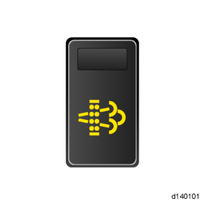
EPA07/10/GHG14 Exhaust – EGR – ATS Manual (DDC-SVC-MAN-0083) | 37 EPA10/GHG14 Aftertreatment System Overview | 37.9 Performing a Parked Regeneration – EPA10/GHG14When the parked regeneration request is accepted, the Diesel Particulate Filter (DPF) Regeneration lamp will turn ON one time for one second and then turn off for the remainder of the parked regeneration. The High Exhaust System Temperature (HEST) lamp will flash for one second every ten seconds and eventually become solid when the tailpipe temperature is above 525°C (977°F).The engine speed will increase to 1100 RPM for all DD Platform engines. The regeneration will take 30 to 40 minutes. The regeneration is complete when the engine returns to low idle and the DPF lamp remains OFF. The HEST lamp will remain ON, but the vehicle may be driven.

    NOTE: A parked regeneration will STOP and the engine will return to low idle if any of the following happens:

    SAVE MONEY ON FUEL FREIGHTLINER CASCADIA

    • The key is turned to the OFF position
    • The vehicle is put into gear
    • The clutch is cycled
    • The parking brake is released
    NOTE: If a parked regeneration is being performed to check NOx conversion, the calculated ambient temperature in the ACM (AS053) must be above 0°C (32°F) or the test will fail.
    NOTE: If the HEST LAMP is FLASHING, a regeneration is in process and the system is coming up to temperature.

How to Check Fault Codes DD15 Freightliner Cascadia

Published / by Mechanic / 5 Comments on How to Check Fault Codes DD15 Freightliner Cascadia

Follow these guidelines to check for fault codes on any Freightliner Cascaida with a DD15 engine.

  1. Key on, Engine off.
  2. Placed unit in neutral.
  3. Locate the square black button on the odometer screen.
  4. Using the black button cycle through the options displayed on the odometer reading until it reads “diagnose”.
  5. Hold the button until the display shows “faults”.
  6. From there it will show you the number of active faults in the system.
  7. Again using the black button cycle through the “faults” to observe the SPN and FMI.

Causes For Onebox/DPF Failures/ATD Checklist

Published / by Mechanic / 1 Comment on Causes For Onebox/DPF Failures/ATD Checklist

A common failure now on all EPA10 DD15 is becoming a one box and DPF failures, these are costly items to repair. To repair these failures correctly you must determine root cause for failure, as these parts will never fail on their own. Find the primary failed part and repair prior to replacing a onebox or DPF’s to prevent repeat failure down the road.

  1. Verify the air filter is installed correctly. Measure the Air Inlet Restriction with a manual gauge under 100% load (do not use the gauge on the air filter assembly). Is the Air Inlet Restriction greater than 18 H2 O”? Repair as required over restriction level.
  2. Pressurize the intake track, including the Charge Air Cooler (CAC) and associated piping, inspecting for leaks. Was a leak found? Repair for any leaks.
  3. Inspect for excessive oil coming out of the turbocharger compressor. If any oil is present Replace Turbo.
  4. With engine OFF, visually inspect the Exhaust Gas Recirculation (EGR) linkage for damage or limited travel. Repair for EGR component Failure.
  5. Using DiagnosticLink® , sweep the Intake Throttle Valve (ITV). Is the ITV stuck or is there limited travel? If a seized valve is found, repair as necessary.
  6. Inspect for exhaust leaks before the Aftertreatment Device (ATD). Are any exhaust leaks found? Repair all exhaust leaks.
  7. Inspect for plugged delta P ports. Are the delta P ports plugged? Clean/replace delta p if found plugged.
  8. Compare Inlet Manifold Pressure (IMP) ______ kPa ______ (psi) and Barometric Pressure (BP) sensor ______ kPa ______ (psi). Are both sensor readings within 10.3 kPa (1.5 psi) of each other? Replace IMP if found readings out of spec.
  9. Get readings of ATD temperature sensors with the ignition ON (key ON, engine OFF). Note coolant temperature. The best way to determine if a sensor has drifted out of range is to check the system with a cooled ATD.
    • Coolant ______ °C (______ °F)
    • DOC in ______ °C (______ °F)
    • DOC out _____ °C (______ °F)
    • DPF out ______ °C (______ °F)
    • SCR in _______ °C (______ °F)
    • SCR out ______ °C (______ °F)
  10. Inspect the CAC Outlet Temperature/Inlet Manifold Pressure (combination) sensor connector for corrosion. Was corrosion found? Repair as required.
  11. ct the IMT sensor connector for corrosion. Was corrosion found? Repair as required.
  12. Perform Idle Speed Balance (ISB) test. Then Perform a Relative Cylinder Compression Test with DiagnosticLink. Look for any internal damage, then proceed according to findings.
  13. Remove DOC inlet pipe from ATD and perform three throttle snaps. There should be one puff of smoke (the size of a basketball) that quickly clears. Is there excessive smoke? If yes, Manually cut cylinders to try and identify an over-fueling injector.

DD15 EPA10/GHG14 Maintenance Intervals

Published / by Mechanic / Leave a Comment
ITEMMILEAGE
Lubricating Filter35,000mi
Lubricating Oil35,000mi
Coolant105,000mi
Coolant Filter105,000mi
Fuel Filter35,000mi
Frame Mounted Filter35,000mi
Top Set/Tune UpInitial top set 100,000mi
Second 500,000mi there after every 500,000mi
Belts175,000mi
Air Cleaner50,000mi
ATD Inspect hardware and all connections every 6 months
Diesel Particulate Filters300,000mi
DEF Pump Filter175,000mi
DEF Pump Air BladderRefill every 24 months

DD Engine Coolant Filters

Published / by Mechanic / Leave a Comment

The coolant filter has been removed from DD platform engines. The change comes with an improved Oil Cooler Module which resides on the front, left-hand side of the engine and houses the coolant pump, thermostat, oil fill, and oil filter. On engines built prior to this change, the coolant filter access cap was located just forward of the oil filter.
The current coolant filter is only partial flow (~15%). Testing showed that coolant and engine protection were not affected by the removal of the coolant filter. Customers will also benefit from reduced maintenance costs by eliminating the coolant filter inspection/replacement cycle.
The new Oil/Coolant Module is NOT backwards compatible on older engines. However, customers may choose to remove the coolant filter on their current engines at the next applicable Preventative Maintenance stop.
The new Oil/Coolant Module became effective with the following approximate change points.
• DD15AT engine s/n 472906S0326388 built on 23-Mar-15.
• DD13 engine s/n 471927S0326736 built on 17-Mar-15.
• DD15TC engine s/n 472909S0327137 built on 17-Mar-15.
• DD16 engine s/n 473908S0327187 built on 19-Mar-15.
Please note that the new oil fill is now connected at the bottom by a flexible tube, which increases the restriction when the engine is filled with oil. Shops using an automatic oil filling machine may need to adjust their flow rate to avoid spills.

Latest Software Levels

Published / by Mechanic / Leave a Comment

GHG – Current Software

MCM – 4.7.0.0 Software w/Fuel Map ZGS001 ACM – 5.57.0.0 Software w/ Fuel Map ZGS001 CPC – r34.00.000
Detroit DT12 Transmission

CPC Production Software is R34.00.000A
TCM Software is NAMT070700
DD13 and DD15 Except for 400/1750 rating, Shift Map P/N A0174488402 ZGS001
DD15 with Integrated Powertrain 400/1750 rating, Shift Map P/N A0174488202 ZGS001
DD16 Shift Map P/N A0174488302 ZGS001

EPA10 – Current Software

MCM – 7.7.1.47 Software w/Fuel Map ZGS001
ACM – 8.7.0.105 Software w/Fuel Map ZGS001
CPC – 22.02 Software

Please note that you must have DiagnosticLink 8.0 to program the new GHG Software

DD Engine EPA07
MCM v13.4.2.0 Software with Fuel Map ZGS003
CPC – r5.03 Software

S60 EPA07
MCM v63.2.1.0 and Fuel Map ZGS002
CPC – r5.03 Software

MBE4000 EPA07
MCM – v13.5.0.0 with Fuel Map ZGS002
CPC – r5.03 Software

MBE900 EPA07
MCM – v11.4 with Fuel Map ZGS005
CPC – r4.03

EPA 10 DDE 15 Regen Log File Normal Values

Published / by Mechanic / 3 Comments on EPA 10 DDE 15 Regen Log File Normal Values
PARAMETERVALUE
Coolant TemperatureAbove 140*F
DOC Inlet Temperature600-725*F
DOC Outlet Temperature1050-1150*F
DPF Outlet Temperature1050-1150*F
SCR Inlet Temperature950-1100*F
SCR Outlet Temperature950-1100*F
DEF Pressure66-85 psi
DEF Air Pressure19-29 psi
Actual DEF Dosing Quantity800-900 g/h
NOx Conversion Efficiency 70-100%
SCR Inlet NOx Sensor200-300 ppm
SCR Outlet NOx Sensor5-25 ppm
DOC Inlet Pressure<1.3 psi(1box) or <1.74 psi(2box)
DPF Outlet PressureAround 1/2 of DOC Inlet Pressure
Engine Speed1100 rpm
Fuel Cutoff Valve100%
Throttle Valve Actual Position75-90%
Fuel Doser Injection Status10-30%
Fuel Compensation Pressure80-90 psi
Doser Fuel Line Pressure15-30 psi
EGR Delta Pressure-0.05 - 0.20 psi
EGR Command Governor Value5%
Jake Brake 1 100%
Actual Fuel Mass100-130 mg/st
Inlet Manifold PressureBarometric Pressure +2-3psi
Actual DPF ZoneDrops to 0(if not already)

Winter Fronts

Published / by Mechanic / Leave a Comment

Reasons to use a winter front:

Winter fronts on DD engines are necessary due to the design of the engine cooling system. The coolant thermostat is on the inlet side of the cooling system on the DD Platform engine and regulates coolant flow from the radiator into the engine. The thermostat regulates coolant flow to control the temperature of the coolant within the coolant circuit. The following benefits are a result from regulating the coolant at the inlet temperature side of the engine:

  • Reduced thermal cycling of the engine
  • Operating temperature of the engine is reached faster
  • Improved vehicle heating because of the better temperature regulation

Dangers of the using the wrong winter front:
Use of a winter front on a DD platform engine, especially those that are fully closed, it’ll cause performance issues and is not recommended on DD engines. Winter fronts can result in the following:

  • Excessive fan run time due to higher CAC outlet temperatures resulting from low air flow through the CAC
  • Increase in fuel consumption
  • Failure of the DEF system heaters to turn on when needed causing fault codes to appear, poor Aftertreament performance and power loss. Worst case engine shutdown.
  • Failure of emission components that will result in a derate and possibly engine shutdown.

Use of a winter front should be avoided as this has been shown to cause false fault codes with the engine and aftertreatment system. This has also been linked to specific component failures that will cause vehicle downtime and lost productivity.


There are two specific situations where a winter front may be temporarily needed:

  • To improve cab heating while idling under extreme cold ambient temperature
  • When the ambient temperature remains below -30°C and the engine is unable to maintain running coolant temperature of 80°C during normal on road operation.

If either of the above situations is encountered, then a winter front may be temporarily used. A minimum of 25% of the grill must be open in sectioned stripes that run perpendicular to the charge air cooler tube flow direction. This assures even cooling across each tube and reduces header-to-tube stress and possible failure. winter front