1. Turn engine OFF, (key OFF, engine OFF).
Do not power wash or steam clean the engine bay in the area of vehicle electrical components, unless specified by vehicle manuals or service literature. Power washing/steam cleaning can permanently damage these components, which could result in fire, personal injury, or property damage.
2. Steam clean the engine.
3. Disconnect the starting power for the engine. Refer to OEM procedures.
4. Remove the air cleaner and the turbocharger inlet pipe and hose. Refer to OEM procedures.
5. Remove air cleaner housing. Refer to OEM procedures.
6. Remove the rocker cover. Refer to section “Removal of the Rocker Cover”
7. Using special tool (J-46392 or W904589046300), bar the engine over until cylinder number one is at Top Dead Center (TDC) compression stroke.
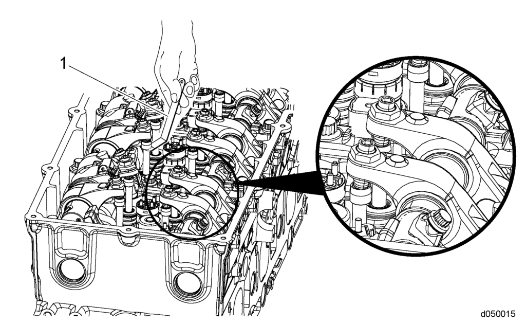
8. Using a feeler gauge (1), lash intake valves one, two and four to 0.4 mm (0.016 in.).1. Figure below displays the old style intake camshaft with 12 lobes and the old style rocker arms. These components were utilized on DD13 engines built before engine serial number HDE0079072 and on the DD15 & DD16 engines built before HDE0077481.
d050015
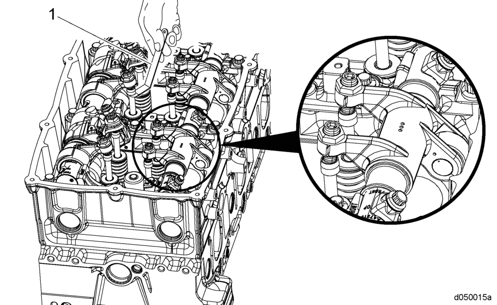
2. Figure below displays the new style intake camshaft with 6 lobes and bridged rocker arms. These components were installed on DD13 engines beginning with engine serial number HDE0079072 and on the DD15 &DD16 engines beginning with engine serial number HDE0077481. The components are not backwards compatible.
d050015a
9. Using a feeler gauge (1), lash exhaust valves one, three and five to 0.6 mm (0.024 in.).
10. Using special tool (J-46392 or W904589046300), bar the engine over 360° until cylinder number six is at TDC compression stroke.
11. Lash intake valves three, five, and six to 0.4 mm (0.016 in.).
12. Lash exhaust valves two, four and six to 0.6 mm (0.024 in.).
13. Torque the locknut valve adjusting screw to 50 N·m (37 lb·ft).
14. Remove any tools used for this procedure.
15. Set the engine brake lash.
DD15 ENGINE BRAKE/ JAKE BRAKE LASH ADJUSTMENT
1. Set the lash on all the exhaust adjusting screws first (all the adjusting screws in direct contact with the exhaust valves).
2. Rotate the engine until a given cylinder is at maximum intake lift. When this is reached, the brake lash can be set on this cylinder.
3. When the engine brake rocker arm is in contact with the exhaust valve, set the lash between the engine brake rocker arm adjusting screw and the actuator piston stem.1. DD15 & DD16 engines built before HDE0077481 use Engine Brake Adjustment tool W470589022300; set the lash to 4.1 mm (0.1614 in.).
2. DD 15 & DD16 engines built starting with HDE0077481 use Engine Brake Adjustment tool W470589042300; set the lash to 4.6 mm (0.1811 in.).
3. DD13 engines built before HDE0079072 use Engine Brake Adjustment Tool W470589022300; set the lash to 4.1 mm (0.1614 in.).
4. DD13 engines built starting with HDE0079072 use Engine Brake Adjustment tool W470589042300; set the lash to 4.6 mm (0.1811 in.).
4. Lash the engine brakes in the following firing order: 1, 5, 3, 6, 2, and 4.
5. Torque the locknut valve adjusting screw to 50 N·m (37 lb·ft).
6. Install the rocker cover